


Want to make racing Hot Wheels even more fun? What if you could measure just how fast your Hot Wheels is going?
In this project inspired by nfarrier, we’re going to create a photogate for a Hot Wheels race track.
Here are the parts you’ll need:
- Arduino Uno + Genuino UNO https://vilros.com/products/arduino-uno-micro-controller?variant=21355380113508
- 200K ohm through hole resistor
- 2K ohm through hole resistor
- White LED w/ high brightness
- Adafruit photo transistor light sensor
- Soldering iron + wire
- 3D printer (optional)
How it Works
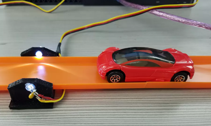
This project uses a photo transistor to detect when a Hot Wheel car reach a certain point on the track. It can also calculate the speed of the car at the position of the sensor.
A white LED is recommended as it makes it easy to see that the device is connected properly and turned on, but you could substitute your preferred LED.
A 3D printer is also recommended but optional. In this first version of this project, nfarrier used a hot glue gun to attach cardboard pieces together to create a holder for the sensor and LED. This works fine, but it’s not very durable.
If you want to calculate the Hot Wheels speed even more precisely, we recommend constructing and utilizing two photogates. Just make sure the distance can be measured by the time detected and displayed in the Arduino serial monitor in order to make the calculations.
Code
Here’s the code you’ll need for this project with just one LED photogate:
/* PhototransistorVoltage Hot Wheels Timer
* Power phototransistor with 5v and GND
* Connect the phototransistors yellow wire into A1
* Optional: Use a piezo buzzer connected to pin 4 and GND.
*/
const int buzzerPin = 4; // other end of buzzer connected to GND
float threshold = 0.25; // voltage where phototransistor shows car is in the way
const int interval = 5; // accuracy of timer in milliseconds
void setup() // Built-in initialization block
{
Serial.begin(9600); // Set data rate to 9600 bps
}
float v1, timerCount;
boolean waitFor2ndTrigger;
void loop() {
tone(buzzerPin, 440*6, 50); // Sound "ready"
timerCount = 0;
waitFor2ndTrigger = true;
v1 = volts(A1); // measure voltage from phototransister in A1
tone(buzzerPin, 880, 150); // Sound for start of waiting for trigger
Serial.println("Waiting for trigger..."); // wait for phototransistor to be dimmed
while (v1 > threshold) {
delay(interval); // otherwise it's too fast to notice button press ((when one is used)
v1 = volts(A1); // measure voltage from phototransister in A1
}
Serial.print("Started..."); // Display "Start"
while (waitFor2ndTrigger) { // count time until phototransistor receives light again
delay(interval); // Delay for defined time
timerCount = timerCount+interval; // Add time to counter
v1 = volts(A1); // check A1 phototransistor
waitFor2ndTrigger = (v1 < threshold); // is "false" when phototransistor receives light again
}
// end timer count and display results
Serial.println("Stopped"); // Display " sec." & newline
tone(buzzerPin, 880, 50); // Sound at finish
delay(80);
tone(buzzerPin, 880, 80);
Serial.print("Final Time = "); // Display "Final Time = "
Serial.print(timerCount/1000); // Display timerCount in #.### format instead of milliseconds
Serial.println(" seconds"); // Display " sec." & newline
Serial.print("Speed = "); // Display "Speed = "
Serial.print(72/(timerCount/1000)); // Display speed based on 72 mm car
Serial.println(" mm/sec"); // Display "mm/sec" & newline
Serial.println(""); // print blank line
delay(3000); // wait 3 seconds and reset
}
float volts(int adPin) // Measures volts at adPin
{ // Returns floating point voltage
return float(analogRead(adPin)) * 5.0 / 1024.0;
}
And here’s the code for the dual photogate version:
/* PhototransistorVoltage Hot Wheels Timer
* Power each phototransistor with 5v and GND
* Connect the 2 phototransistors yellow wires
* into A1 & A2 to detect start and stop of car.
* Use a piezo buzzer connected to pin 4 and GND.
*/
const int buzzerPin = 4; // other end of buzzer connected to GND
float threshold = 0.25; // voltage where phototransistor shows car is in the way
const int interval = 10; // accuracy of timer in milliseconds
void setup() // Built-in initialization block
{
Serial.begin(9600); // Set data rate to 9600 bps
}
float v1, v2, timerCount;
boolean v1trigger, waitFor2ndTrigger;
int count=0;
void loop() {
tone(buzzerPin, 440*6, 50); // Sound "ready"
timerCount = 0;
count = 0;
v1 = volts(A1); // measure voltage from phototransister in A1
v2 = volts(A2); // measure voltage from phototransister in A2
Serial.println("Waiting..."); // wait for either phototransistor to be dimmed
while (v1 > threshold && v2 > threshold) {
delay(interval); // otherwise it's too fast to notice button press
v1 = volts(A1); // measure voltage from phototransister in A1
v2 = volts(A2); // measure voltage from phototransister in A2
}
v1trigger = (v1 < threshold); // find which was triggered
Serial.println("Start"); // Display "Start"
tone(buzzerPin, 880, 150); // Sound for start of clock
v1 = volts(A1);
v2 = volts(A2);
waitFor2ndTrigger = true; // check only A1 phototransistor
while (waitFor2ndTrigger) { // count time until 2nd probe is triggered
delay(interval); // Delay for defined time
timerCount = timerCount+interval;
v1 = volts(A1);
v2 = volts(A2);
if (v1trigger) {
waitFor2ndTrigger = (v2 > threshold); // check A2 phototransistor
}
else {
waitFor2ndTrigger = (v1 > threshold); // check A1 phototransistor
}
}
// end timer count and display results
tone(buzzerPin, 880, 50); // Sound at finish
delay(80);
tone(buzzerPin, 880, 80);
Serial.print("Final Time = "); // Display "v Final Time = "
Serial.print(timerCount/1000); // Display timerCount in #.### format
Serial.println(" sec."); // Display " sec." & newline
Serial.println(""); // print blank line
delay(3000); // wait 3 seconds and reset
}
float volts(int adPin) // Measures volts at adPin
{ // Returns floating point voltage
return float(analogRead(adPin)) * 5.0 / 1024.0;
}
3D Model
If you’d like to check out the 3D model for the custom-built photogate, check out this guide.
Wiring for One Photogate or Two
This is how you’ll want to wire all your components together for this project with one photogate.
And here is how you’ll want to do the wiring for two photogates.
Your Hot Wheels should now be ready to race and measure! For more information on this project, you can watch this video with the Hot wheels track using one photogate. Or, just refer to this project tutorial for more detailed information on all versions of this project.
All of us here at Vilros hope you have hours of fun with your new race track with photogates. When you’re ready to try a new project, make sure to come back to our Vilros Projects blog for more fun ideas with Arduino and Raspberry Pi.